- Project Management Network Diagram Software Microsoft
- Project Management Network Diagram Software Online
- Project Management Network Diagram Software Examples
- Project Management Network Diagram Software Download
- Project Management Network Diagram Software Online
Activity Network Diagram
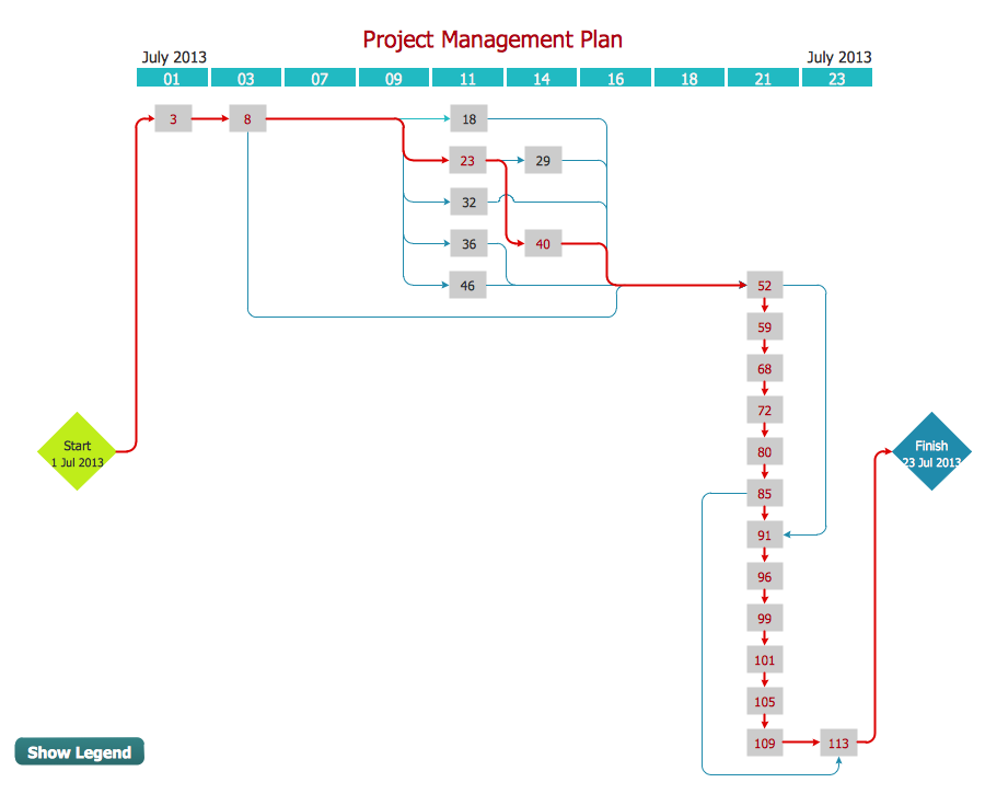
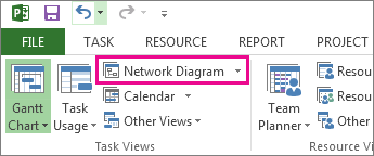
Find your Network diagram software template, contract, form or document. Easy to use Word, Excel and PPT templates. Telecommunication Network Diagrams solution extends ConceptDraw DIAGRAM software with samples, templates, and great collection of vector stencils to help the specialists in a field of networks and telecommunications, as well as other users to create Computer systems networking and Telecommunication network diagrams for various fields, to organize the work of call centers, to design the GPRS. A Network Diagram is a graphical way to view tasks, dependencies, and the critical path of your project. Boxes (or nodes) represent tasks, and dependencies show up as lines that connect those boxes. After you’ve switched views, you can add a legend, customize how your boxes appear, and print your Network Diagram. See full list on pmi.org.
An Activity Network Diagram (AND) is also called an Arrow Diagram (because the pictorial display has arrows in it) or a PERT (Program Evaluation Review Technique) Diagram, and it is used for identifying time sequences of events that are pivotal to objectives. In Critical Path Analysis, this helps the teams to comprehend the specific event sequences driving time requirements for objective achievement. Activity Network Diagrams are also very useful when a project has multiple activities that need simultaneous management.
Activity Network Diagrams started out as an engineering and construction project management tool. Critical Path Analysis draws on this methodology to identify and standardize medical management activities.
An Activity Network Diagram helps to find out the most efficient sequence of events needed to complete any project. It enables you to create a realistic project schedule by graphically showing
- the total amount of time needed to complete the project
- the sequence in which tasks must be carried out
- which tasks can be carried out at the same time
- which are the critical tasks that you need to keep an eye on.
EdrawMax
All-in-One Diagram Software

- Superior file compatibility: Import and export drawings to various file formats, such as Visio
- Cross-platform supported (Windows, Mac, Linux, Web)
Example of Activity Network Diagram
A project is composed of a set of actions or tasks which usually have some kind of interdependency. For example, before an axle can be turned, it must first be designed, the metal must be purchased, etc. This type of complex system is much easier to understand through the use of diagrams than through textual description, as actual interconnections between tasks can be shown. You can draw the activity network diagram easily with Edraw software.
The Activity Network diagram displays interdependencies between tasks through the use of boxes and arrows. Arrows pointing into a task box come from its predecessor tasks, which must be completed before the task can start. Arrows pointing out of a task box go to its successor tasks, which cannot start until at least this task is complete.
Activity Network Diagram Drawing Rules
All the preceding activities must be completed before the project can begin.
The arrows represent the logical precedence of the project.
History of Activity Network Diagram
It was developed by the U.S. Department of Defense. It was first used as a management tool for military projects. It was Adapted as an educational tool for business managers.
More Related
The Network Diagram became the name for the PERT Chart view that you found in Project 98.
nn'nnm x Project doesn't really produce a PERT chart, but you can use an add-on product — PERT ( book.
rn Rfiivi lOT PERT chart Expert. Try out a sample using the demo that's on the CD-ROM of this
The Network Diagram view, shown in Figure 6-12, has less to do with timing than it has to do with the general flow of work and the relationships between tasks in your project. This view makes it easy for you to evaluate the flow of your project and to check task dependencies.
- Figure 6-12: The Network Diagram view.
Project Management Network Diagram Software Microsoft
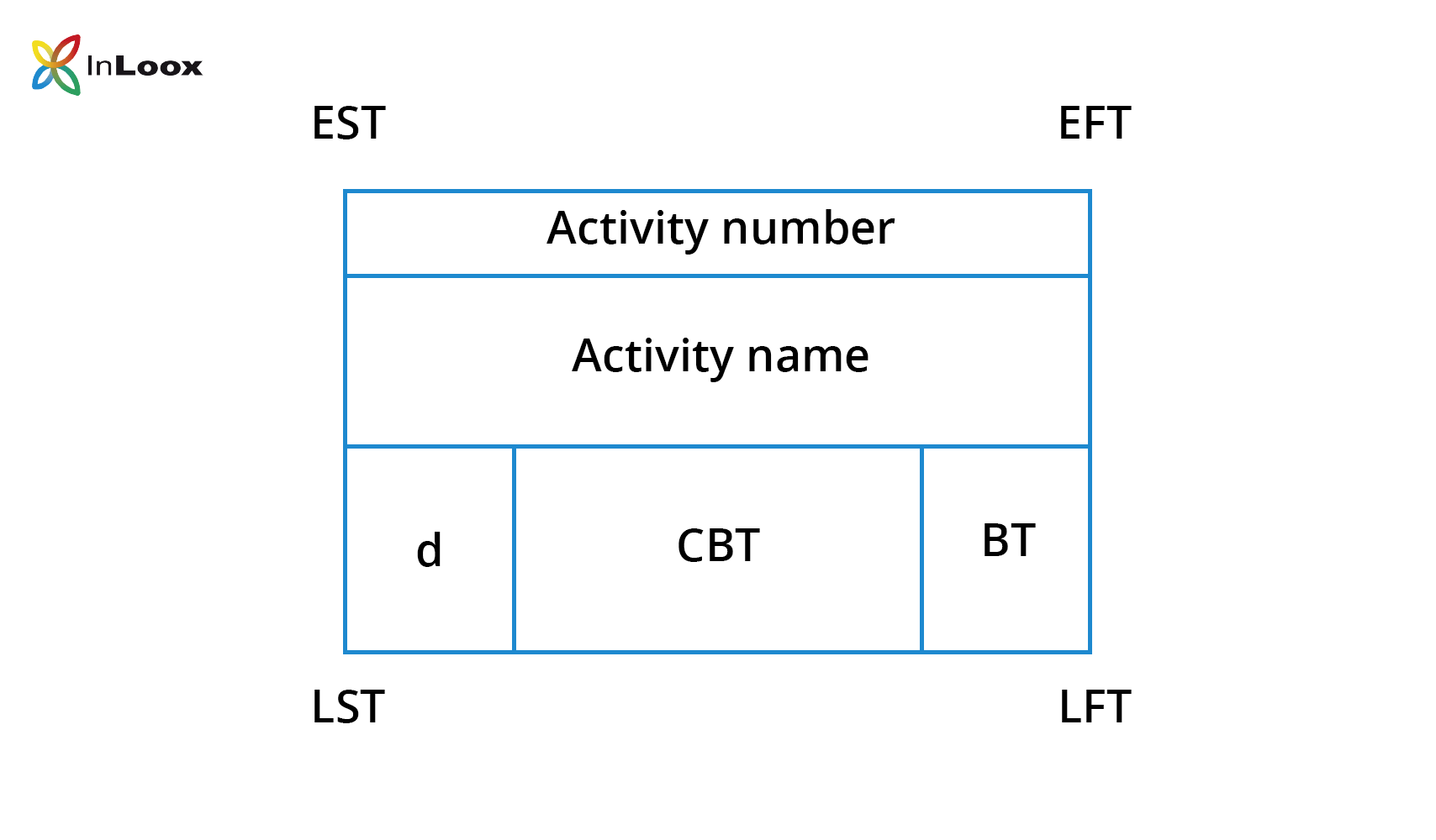
Each node in the Network Diagram view represents a task in your project. For Figure 6-13, I used Project's Zoom command (ViewOZoom) to enlarge a node so that you can see the details. A node contains the task name, duration, task ID number in the sequence of the project outline, start date, finish date, and, if assigned, the resource(s). The thickness of the border and color of each node represents different types of tasks — that is, critical tasks are red and thick borders, while non-critical tasks are blue and have thin borders. You can determine (and change) the meaning of node shapes in the Box Styles dialog box (choose FormatOBox Styles). The lines that flow between the nodes represent dependencies. A task that must come after another task is completed, called a successor task, appears to the right or sometimes below its predecessor.
- Figure 6-13: You can see task details when you examine the nodes of the Network Diagram.
You couldn't filter Project 98's PERT Chart view; however, a filtering feature was added in Project 2000. While viewing the Network Diagram, choose ProjectOFiltered for and select the filter that you want to use.
You read more about filtering in Chapter 7.
Project Management Network Diagram Software Online
Cross-Reference
Starting in Project 2002, you can group tasks in the Network Diagram view; this is similar to the way that you can group tasks in the Gantt view. Colored bands separate the nodes. For example, in Figure 6-14, you see tasks grouped by duration. Open the Project menu and point to Group to see the groups that are available by default. You also can create your own groups.

- Figure 6-14: You can group tasks in a variety of ways in the Network Diagram view.
You can now display indicators and custom fields in Network Diagram nodes. You add the node information to an existing node template, or you create a new template. Follow these steps to display indicators or custom fields in nodes:
1. In the Network Diagram view, choose FormatOBox Styles.
2. Click the More Templates button, as shown in Figure 6-15.
3. In the Data Template dialog box, edit one of the existing templates or create a new template from scratch.
4. In the Data Template Definition dialog box, shown in Figure 6-16, click in the cell where you want either indicators or a custom field to appear. Project adds a list box indicator to the cell, thus enabling you to open the list and select the information that you want to appear in that cell of the node. In Figure 6-16, I'm adding the Indicators field to the nodes.
- Figure 6-15: In the Box Styles dialog box, select the template that you want for the nodes in the diagram.
- Figure 6-16: Add information to a cell of the Network Diagram node.
Note You can't edit the Standard template, but you can copy it, as I did in Figure 6-15.
5. Click OK to redisplay the Data Template dialog box.
Project Management Network Diagram Software Examples
6. Click Close to redisplay the Box Styles dialog box.
Project Management Network Diagram Software Download
7. From the Data template list, select the template that you edited or created.
8. Click OK. You see the new field on appropriate nodes. In Figure 6-17, a Note indicator appears only in the Determine budget task, because no other tasks in view have notes.

- Figure 6-17: A Network Diagram that displays indicators in the nodes.
Project Management Network Diagram Software Online
Continue reading here: Descriptive Network Diagram

Was this article helpful?
Comments are closed.